RANDOM SUBDIVIDER MANUAL
Random Subdivider is a time signature based trigger sequencer with a built-in random source for added chaos. It can quickly produce a variety of traditional rhythms as well as more experimental generative trigger streams.


Panel Controls
NUMERATOR KNOB
The Intervalic makes it easy to dial in the exact time signature you desire. From 1-7, this knob controls how many pulses the Denominator period consists of.


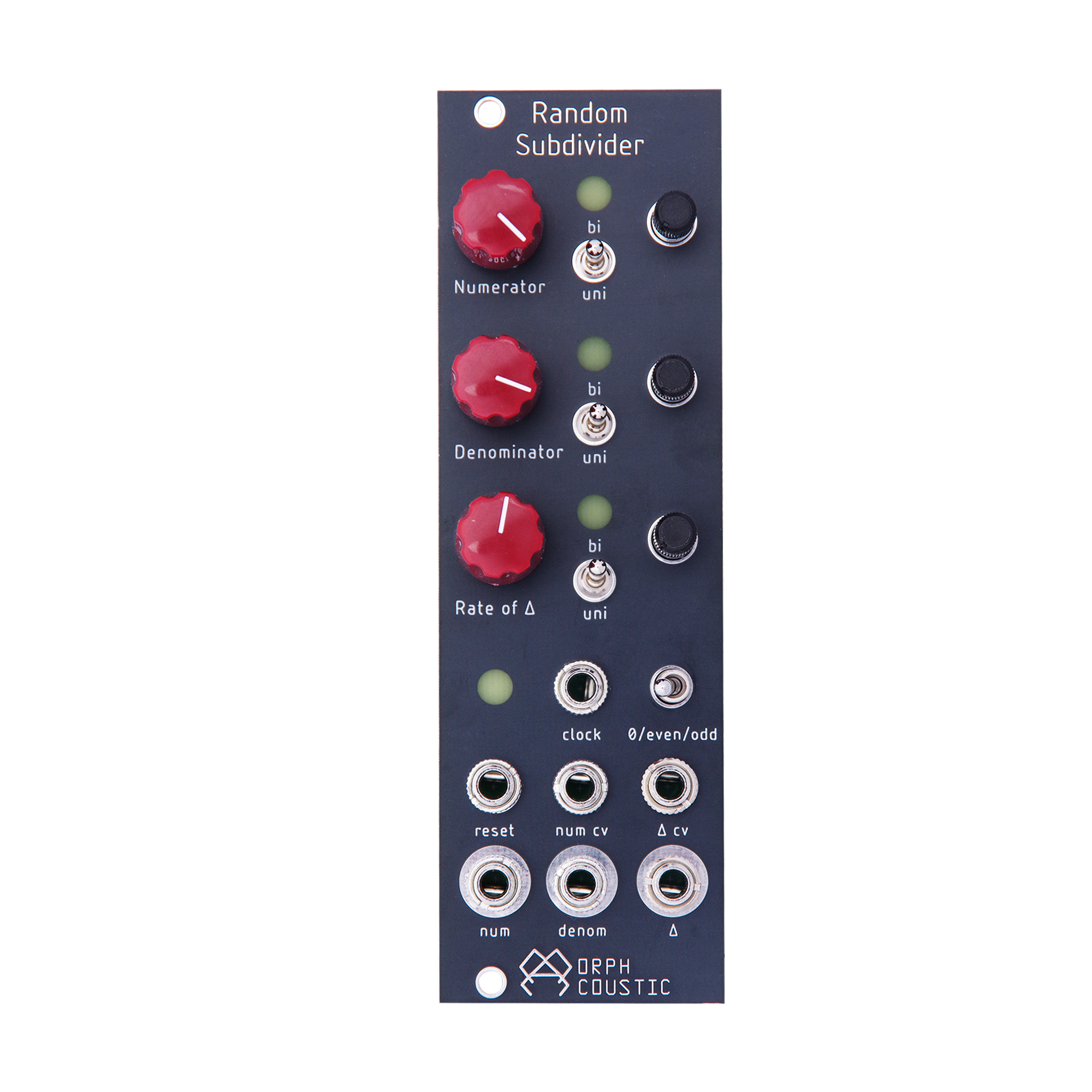
DENOMINATOR KNOB
This knob controls how many pulses a "measure" is. It is the amount of clocks read before the measure is finished. From left to right, the knob selects 5, 4, 3, 2, 1.5 (dotted), and 1.

To dial in a 3/4 time signature, for example, set the numerator to 3 and the denominator to 4.
RATE OF CHANGE KNOB
The Rate of Change knob controls the built in random source. It will determine the number of Denominator pulses after which a new random value is sampled. From left to right, the values are 1, 2, 3, 4, 6, and 8.
RANDOM AMOUNT TRIMMERS
The 3 trimmers to the right of each knob determine the amount of random modulation applied to each of their respective controls. Fully counter-clockwise you will hear no randomness applied to the signal. Fully-clockwise will give the maximum modulation.
UNIPOLAR/BIPOLAR SWITCH
These switches determine whether there will be unipolar or bipolar modulation of the respective channel by the Random Amount trimmers.
EVEN/ODD SWITCH
This is a 3 position switch: Off/Even/Odd. When set to Even or Odd, it will lock the output of the clock to that divisor. For example, when set to Even, you will only generate divisors of 2, 4, 6, 8 etc.
Inputs
CLOCK INPUT & LED
Patch your clock in here. The LED to the left of the Clock input will display the current rate. If you unpatch this input, the clock will still remember its last rate as well.
RESET INPUT
Patch a trigger to this input to reset the pattern, allowing for repeating and more musical sequences.
NUMERATOR & RATE OF DELTA CV INPUTS
These are the modulation inputs for the 3 knobs. All inputs are +/- 5V. Patch your LFO’s here!
Outputs
TRIGGER OUTPUTS
These are the Outs for each the the 3 channels. LEDs next to the corresponding knobs display the trigger pulses.